Power and Temperature Effects
April 10, 2014
Background
Valves are subjected to a wide spectrum of temperatures, an accumulation of fiuld, ambient and
power conditions.
Although our valve design allows for continous duty cycling, solenoid require more power to
energize than to remain energized or hold, resulting in the solenoid coils getting hot when
energized repeatedly in short time intervals at the rated voltage.
Even at cooler ambient temperatures, the inherent nature of PTFE is such that it can ‘COLDFLOW’,
potentially causing the valve body distortion and loose retaining screws.
Cause / Effect
Heat generated in the solenoid from the on-off cycling is transferred to all parts of the valve,
including the PTFE body; the different expansion rates of the PTFE (which is a higher than that
of the other materials), steel and stainless steel, cause misfits between the parts, ranging from
micro (no problem) to macro. This can cause defective operation, most commonly detected as
internal leakage between the seal and seat.
Sometimes as the heat is taken away, the PTFE body goes back to its original dimensions, and
sometimes, permanent deformation occurs. Retaining screws may also become loose.
Remedy
Under such circumstances, we recommend heat-sinking the solenoid portion of the valve.
Aluminum heat sinks can be attached onto the top of the solenoid or the solenoid can be
mounted onto the chassis of the instrument to dissapate heat.
Another ofter-used method, and one that we prefer, is to power the valves on and then go
down to what is called a ‘HOLDING VOLTAGE’. Assume a 12VDC valve is energized with an
unregulated voltage (approximately +25% of rated voltage). Once applied, the valve changes
state. As soon as this occurs, go to a voltage of between one-quarter to one-third of the rated
voltage (3 to 4VDC).
Note that the valve is designed to maintain its energized position, even at this low voltage, due
to its efficient coil design and characteristics. The valve will then run cool.
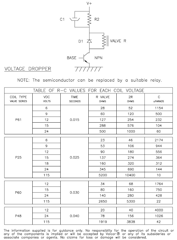
Attached drawing UKSP9810 shows just one such simple R-C circuit with a Resistor and
Capacitor in parallel with each other and this R-C is connected to one leg of the flying leads
of the valve. The R-C is minimal in cost, and provides the benefits of eliminating unnecessary
replacements and preventing heat transfer to media. Please note, the method shown is only one
of many that could be used; do not use PWM, as vibration can damage the valve seat.
Recent Comments