Back in the day of drafting boards and slide rules, the process for developing new fluid control components was essentially an entirely manual process. A design was conceived, piece part and assembly drawings were detailed, and prototype parts fabricated to the prints. The prototype component was assembled and tested, with the resulting performance compared to the desired specifications. The engineer and technician would then tweak or alter the dimensions of the most critical parts to align the performance of the prototype to the design specifications. This was a largely hit or miss process, which consumed substantial time and cost until the prototype performance met the specifications. Once satisfied with the performance of the first prototype, several Gen 2 prototypes were put together, and their performance evaluated. Frequently, the Gen 2 prototypes’ performance differed from the original prototype. More time and money were spent retesting the prototypes with modified or new parts until the performance met the specification. Technology has evolved substantially since the good old days of Iterative Design Engineering. Today’s superior virtual digital technology takes the guesswork out of the equation, greatly reduces the design and development timeline, and minimizes related costs in the new product’s creation. Using digital iterative design not only speeds up the design process and controls costs but yields a substantially better valve in terms of performance and value. By the time a prototype is built, engineers have a good feeling that its performance meets spec or is pretty close.
Valcor Engineering Corp. uses a virtual digital process known as Model-Based Systems Engineering (MBSE). MSBE is a design process that enables engineers to execute the design of complex electromechanical systems by creating a Digital Twin of the new valve. MBSE is used to design and evaluate the performance of new fluid control components before a single part is fabricated. This level of design evaluation and visualization are capabilities never imagined by the engineers of yesterday.
Historically, sophisticated mathematical modeling and simulation capabilities required the use of High Performance Computing (HPC) systems like Cray supercomputers, which were available only to a select few national labs, academic research institutions, and Fortune 500 companies who had the capital and talent required to use them. Today, the tools required to enable MBSE are readily available to most companies; Valcor relies on these tools to design and create new fluid control components for the most demanding applications.
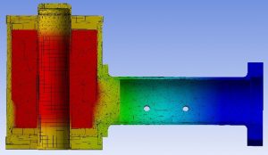 Thermal Analysis of Coil Generated Heat
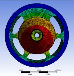
FEA Analysis of Orifice Deformation
To initiate the creation of a new solenoid valve, Valcor engineers start by using SolidWorks CAD/CAE 3D solid modeling software by Dassault Systèmes. The 3D modelling feature of the software greatly assists in establishing the critical dimensions of the parts required for the new valve and evaluating how they all fit together.
Once the parts are designed, Valcor engineers turn to Ansys Finite Element Analysis (FEA) software to evaluate them. The FEA process for each critical part of the assembly ensures that it is robust and appropriate for service in the new valve. FEA identifies areas of unacceptable stress, as well as areas with dimensional weaknesses. The FEA process is used for thermal analysis and structural evaluation including stress, deflections, and distortions. Simultaneously, preliminary vibration analysis is performed using MathCad and a subsequent FEA model is analyzed.
The engineering team then uses FEA to perform fatigue analysis on each part using the solid model generated by SolidWorks. Fatigue analysis is used to determine the usable life of each part. The information derived can then be used to predict the need for periodic maintenance or replacement in actual use.
Several other tools within the Ansys product family are used to assist in the design process. One of these tools used for electromagnetic simulation is EMag. Utilizing this module allows the engineer to virtually simulate the electromagnetic and electromechanical forces in the solenoid design. EMAg assists with the evaluation of pull-in and response time characteristics related to material selection and parts geometry. Response time is how fast the valve moves from one state to another: like fully open in a normally closed valve. It further enables the evaluation of magnetic flux related to bobbin and coil design. With over a decade of use, Valcor has a built a comprehensive database of analytics providing the engineers with an extremely high level of confidence that the new coil designs meet the performance specifications prior to prototyping.
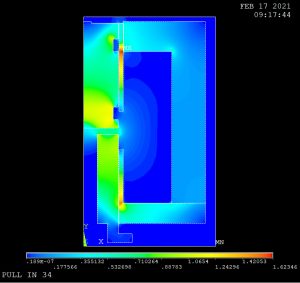 EMag Model of Magnetic Flux Field
Computational Fluid Dynamics (CFD) software is used to model the flow characteristics of the new design. Ansys Fluent and CFX modules integrate the individual parts into a virtual working model of the new valve, allowing engineers to evaluate its theoretical performance against the customer’s specifications. Tweaking the tolerances and dimensions of the subcomponents and evaluating the changes on performance will ultimately yield a design that moves to the prototype stage.
Valcor uses MATLAB/Simulink to further enhance the evaluation of the Digital Twin. These tools enable the engineering team to model response time, forces acting on critical components of the valve, pressures, flow rates, and determine the acceleration of a particular component of the new valve. Simulink collects the data used to analyze the design, and MATLAB controls the virtual model’s performance based on data inputs from Simulink
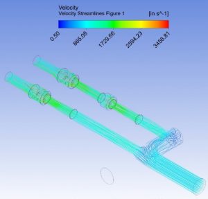 Modeling of Velocity Streamlines Though A Manifold
Once the engineers are satisfied with the performance of the Digital Twin, they release the drawings for use in fabricating the piece parts needed to build prototypes. The completed prototypes are then built. Their performance is tested and compared to the theoretical performance of the Digital Twin. Here, the prototype test results are plotted against the theoretical performance of the valve. By making changes to the critical part dimensions and profiles in CAD and running the simulation model again, the design moves closer to meeting spec. With relatively few iterations of the physical hardware, a design that meets specifications can be arrived at quickly, cost effectively and moved into production with minimal effort.
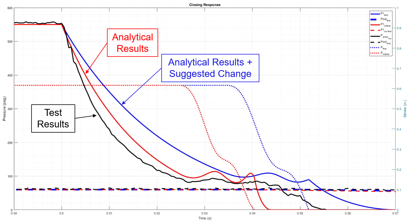
Virtual performance (red trace) plotted against actual test data (black trace), and analytical results after changing the Digital Twin design (blue trace)
As part of the value engineering process, Valcor uses the Digital Twin to optimize the manufacturability of the valve as well. Design changes are made to make the valve easier to assemble without affecting performance, minimizing the need for special fixtures and tools to build the production valve efficiently.
Once the valve design performs to the customer’s specification, the final drawings are released. Valcor’s manufacturing team can generate computer aided manufacturing (CAM) programming for each of the parts used in the valve assembly. Computer numerical control (CNC) programmers will review the programming, and occasionally modify it to suit the specific needs of the CNC machining centers. However, utilizing the MATLAB generated programming eliminates the task of CNC programmers developing the programming for each part from scratch. The end result is the manufacture of quality parts that meet print and are ready for assembly in the final product.
Once released to production, Valcor relies on actual test data to create a feedback loop to the Digital Twin. The feedback allows Valcor to study the performance of the valve in its intended use, affirm suitability of the design, and enabling modification to it when application parameters change. At this point, the engineers anchor the theoretical model to the actual test data. This helps them refine their tools and can be carried over to future analysis and product design.
Valcor Engineering Corporation is a widely recognized leader in providing custom engineered fluid control, motion control and integrated systems solutions for Aircraft and Space applications. Our comprehensive family of products include fluid and motion control components and fuel tank inerting systems. Valcor solenoid valves and regulators are used for hydraulic, propellant, thruster, and fuel control. Valcor also offers a broad selection of fluid control components for ground support equipment and launch systems. Valcor’s Motion Control group offers an extensive portfolio of brakes and clutches to control rotary motion, whether it is on an aircraft braking system, wing flaps, elevators or rudder. Valcor’s fuel tank inerting systems protect fixed wing and rotor aircraft fuel tanks from explosion when penetrated by projectiles.
May we use our experience to help solve your fluid control application? We do the hard stuff!
Recent Comments